
Measuring Ride-by-Wire Delay: From Grip Twist to Throttle Plate Movement
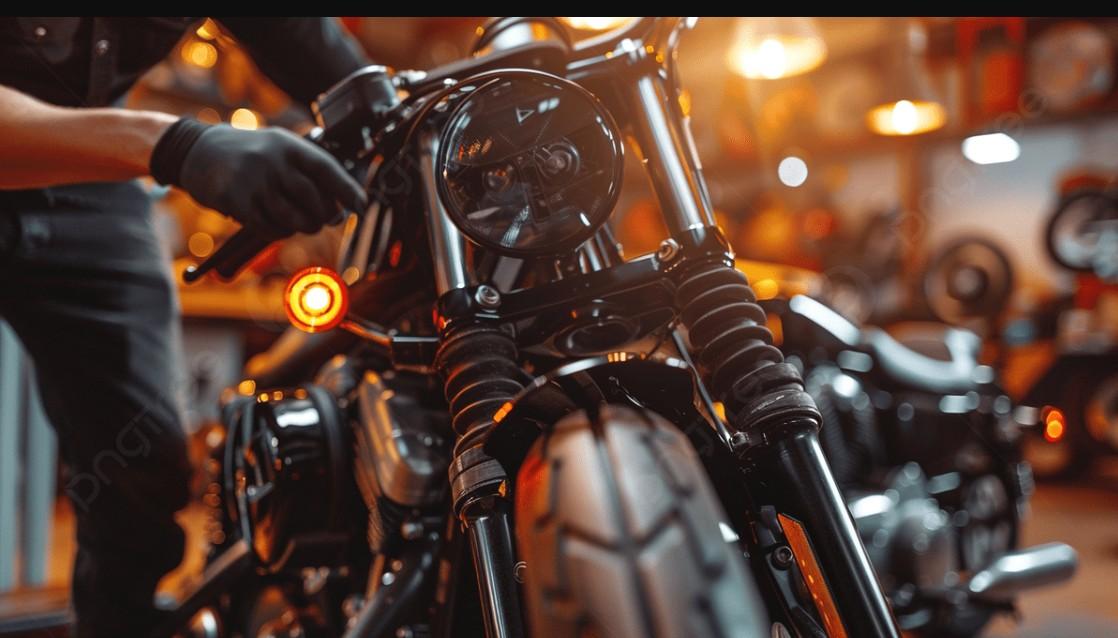
Modern motorcycles have largely abandoned mechanical throttle cables in favor of Ride-by-Wire (RbW) electronic throttle control systems. While RbW enables sophisticated safety features like lean-angle-sensitive traction control, multiple riding modes, and auto-blippers, it introduces a subtle physical phenomenon: electronic latency. Unlike a steel cable that physically pulls the throttle butterfly open in real-time, an electronic system processes signals through sensors, analog-to-digital converters, engine control units (ECUs), and stepper motors.
For performance tuners, track riders, and diagnostic technicians, measuring this delay is not merely an academic exercise. High latency can cause unpredictable throttle response, mid-corner instability, or hesitation during aggressive downshifts. Understanding how to quantify the exact microsecond or millisecond gap between your right wrist moving and the throttle plate opening allows you to diagnose failing sensors, evaluate aftermarket ECU flashes, or optimize system parameters.
1. Understanding the Signal Pipeline in Electronic Throttles
To measure latency accurately, you must first map the electronic and mechanical path the signal travels. The process begins at the handlebar, where a Twist Grip Position Sensor (TGPS)—typically utilizing dual Hall-effect sensors or potentiometers—converts mechanical rotation into dual voltage signals. These signals travel directly to the ECU, which acts as the central processing hub for throttle requests.
[Twist Grip (TGPS)] ──(Analog Signal)──> [Engine Control Unit (ECU)] ──(PWM Signal)──> [Throttle Actuator (TPS)]
Once received, the ECU executes several operations before moving the throttle plate:
-
Analog-to-Digital Conversion: Reading dual sensor voltages for redundant fault-checking.
-
Map Lookup & Strategy: Cross-referencing requested throttle position against gear, engine speed, coolant temperature, and selected ride mode (e.g., Track vs. Rain mode).
-
Safety Rules Checking: Verifying traction control and wheelie control parameters.
-
Actuator Signal Generation: Sending a Pulse Width Modulation (PWM) signal to the DC servo motor inside the Throttle Body Assembly.
-
Mechanical Sweep: The motor rotates the throttle shaft, verified by a Throttle Position Sensor (TPS).
Every stage in this chain adds microsecond-level delays, accumulating into a total latency that can range from 15 to over 100 milliseconds depending on the motorcycle's manufacturer and firmware configuration.
2. Tools and Equipment Required for Precision Measurement
Measuring electronic delay requires high-speed diagnostic gear capable of capturing rapid signal changes. Standard OBD-II scanners or diagnostic software update too slowly (often 10 Hz to 50 Hz refresh rates) to capture real-time latency. Instead, hardware-level signal logging is essential.
Here is the essential toolkit required for accurate signal capture:
-
Multi-Channel Digital Storage Oscilloscope (DSO): A minimum 2-channel oscilloscope with at least 1 MS/s sampling rate and waveform capture capabilities.
-
Back-Probe Pins: Ultra-fine probe tips to tap into ECU and sensor wiring harnesses without stripping insulation.
-
Rotary Encoder or High-Speed Optical Sensor (Optional): Mounted to the throttle grip to capture mechanical physical displacement simultaneously with electrical output.
-
High-Speed Camera (240 FPS to 1000 FPS): Used for physical visual confirmation of mechanical movement relative to wrist action.
Before probing wires, ensure you possess a foundational understanding of motorcycle electrical systems, sensor pinouts, and signal tracing. Developing hands-on diagnostic skills through a targeted motorbike maintenance course will help you read wiring schematics correctly, prevent short circuits, and accurately tap into live ECU lines without damaging delicate electronics.
3. Step-by-Step Measurement Procedure
Executing this test requires connecting your measurement equipment directly to both the input side (twist grip) and output side (throttle body) of the system.
Follow these step-by-step instructions to capture reliable latency data:
-
Identify Signal Wires: Consult your motorcycle's factory service manual to locate the main signal line for the Twist Grip Position Sensor (TGPS 1) and the primary Throttle Position Sensor (TPS 1) feedback wire at the throttle body.
-
Back-Probe Channel 1: Connect Channel 1 of your oscilloscope to the primary TGPS signal line at the handlebar or ECU connector. Set the trigger to rising edge.
-
Back-Probe Channel 2: Connect Channel 2 of your oscilloscope to the return signal wire of the physical TPS located on the throttle body assembly.
-
Configure Scope Settings: Set the voltage scale to 0–5V DC on both channels. Set the time base to 10 ms/div or 20 ms/div to capture a clear, zoomed-in view of rapid voltage transitions.
-
Simulate Snap Throttle: Turn the motorcycle ignition ON (engine OFF to prevent engine acceleration during testing). Perform a rapid snap-open movement of the throttle grip.
-
Capture Waveform: Freeze the oscilloscope display once both voltage curves sweep from idle baseline to wide-open throttle (WOT).
4. Analyzing Data and Interpreting Lag Results
With the oscilloscope trace captured, measuring the delay is straightforward using on-screen time cursors. Position Cursor A at the exact moment Channel 1 (TGPS) begins its upward voltage slope, indicating the initiation of grip movement. Place Cursor B at the moment Channel 2 (TPS) begins its voltage rise, signaling physical movement of the butterfly valve.
Channel 1 (TGPS): ───/▔▔▔▔▔▔▔▔▔▔▔▔▔▔▔▔▔▔▔▔▔▔▔▔▔▔▔▔
| <--- Delay (Δt) ---> |
Channel 2 (TPS) : ──────────────────────────/▔▔▔▔▔▔
The time delta (t) between these two points represents your system's total processing and actuation delay.
Analyzing your findings generally yields three distinct outcome ranges:
-
Below 20 ms (Exceptional): Characteristic of race-spec ECUs or aggressive Sport modes. The delay is virtually imperceptible to the rider.
-
20 ms to 50 ms (Standard): Common for modern street production motorcycles in standard riding modes. Offers a balanced, smooth power delivery without feelable lag.
-
Above 60 ms (Sluggish): Often found in conservative Rain/Wet modes or indicates potential mechanical binding, low battery voltage, or a degrading throttle servo motor.
By isolating mechanical displacement from electronic signal propagation, you can pinpoint whether responsiveness issues stem from software mapping, sensor wear, or physical friction in the mechanical butterfly shaft assembly.
5. Optimizing and Mitigating System Latency
Once you have quantified your ride-by-wire delay, several diagnostic and tuning strategies can help reduce latency or improve response consistency. High latency is not always caused by firmware; physical and electrical factors often play a major role.
To minimize electronic and mechanical throttle response lag, consider the following optimization steps:
-
Verify System Voltage: Servo motors operate slower under lower voltage. Ensure the battery and charging system output a stable 13.5V to 14.4V DC.
-
Clean & Lubricate Throttle Bodies: Carbon buildup around the butterfly plates creates friction, forcing the actuator motor to work harder and slowing down initial movement.
-
Calibrate Throttle Position Sensors: Perform an ECU throttle zero-point reset procedure to ensure the ECU immediately recognizes the smallest movement of the twist grip.
-
Reflash ECU Throttle Maps: Factory software often intentionally dampens initial throttle opening speeds for emissions control and smoothness. Custom ECU flashing can unlock 1:1 direct mechanical-style response curves for track applications.
Regular testing and systematic optimization ensure your ride-by-wire system operates at peak precision, delivering immediate, predictable power whenever you roll on the throttle.

 Arabic
 French
 Spanish
 Portuguese
 Deutsch
 Turkish
 Dutch
 Italiano
 Russian
 Romaian
 Portuguese (Brazil)
 Greek